TI-83 Raspberry PI Python module
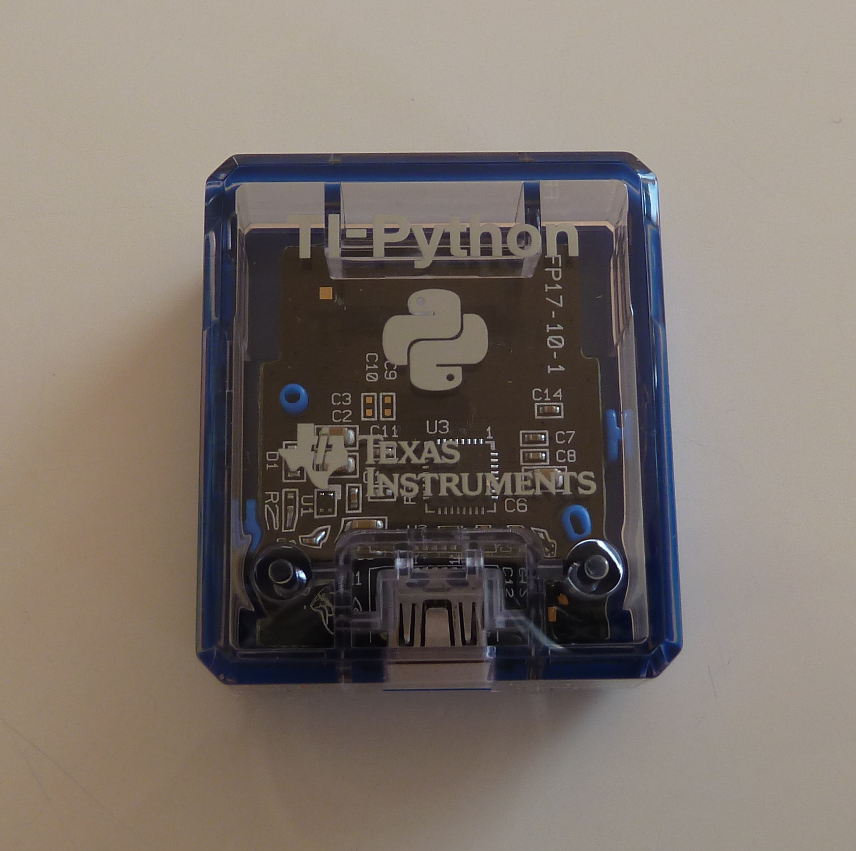
The TI-83 Python module
The module was released as an add-on to the calculator to add a Python interpreter. There was a lot of questions about it, and it was found that it is running a custom CircuitPython
Dumping the firmware
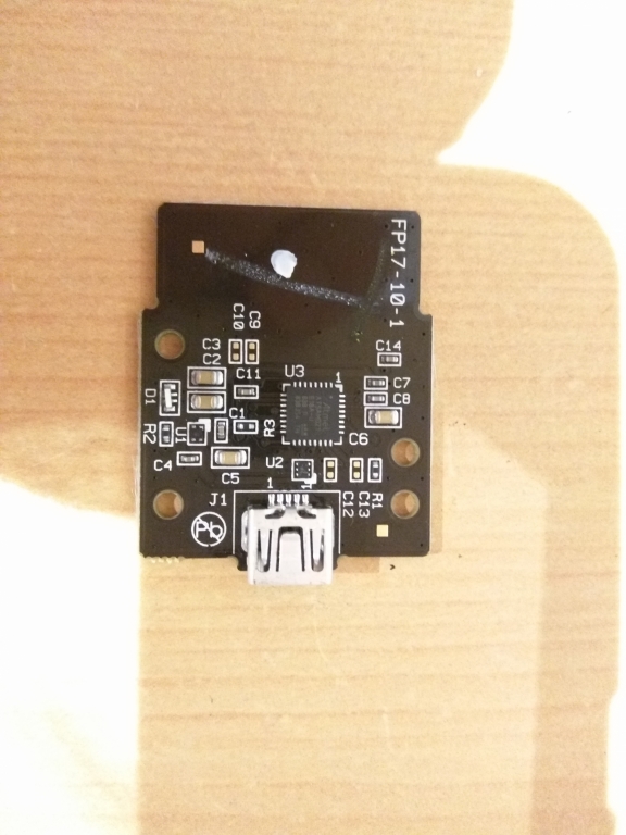
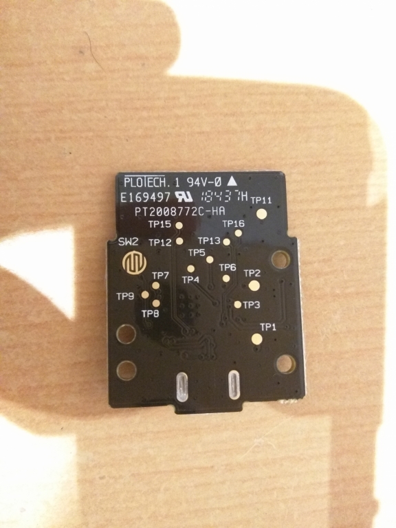
Before discovering the bootloader trick, I dumped pretty easily the firmware, using a BlackMagicProbe and test points TP7 and TP8 on the back of the modules. This correspond to the SWD debug interface (SWDIO on TP7 and SWDCLK on TP8).
 |
 |
Restoring it on a Arduino Zero Clone worked very well. It was found later that the firmware is also working on Adafruit Trinket M0 and other SAMD21 boards. See TI-Planet thread for more informations.
The bootloader
There is an UF2 bootloader on the module, which seems to be a modified version of uf2-samdx1. It is identified by the file INFO_UF2.TXT :
UF2 Bootloader v1.0.3U SFRO
Model: TI-Python Adapter
Board-ID: TI Python Adapter
The USB VID/PID are specific to Texas Instruments. By changing the default ones, the calculator accepts the bootloader, but got stuck trying to update the module in a loop. By using an older version (git tag v1.23.0), the calculator is accepting it and updates the module flawlessly.
Replacing the original firmware by a custom one
Flashing a stock CircuitPython firmware, even by using TI bootloader was working very well, but it was not detected by the Python application on the calculator. Again, after altering CircuitPython USB VID/PID with the ones from the original firmware was the key, but then the calculator just want to upgrade the module using its own version, so no luck here. There was a lot of concern about the usability of the module (see TI-Planet post), and as I am curious, I wanted to find how the calculator is detecting that the module is not running it’s official firmware.
Trivial things
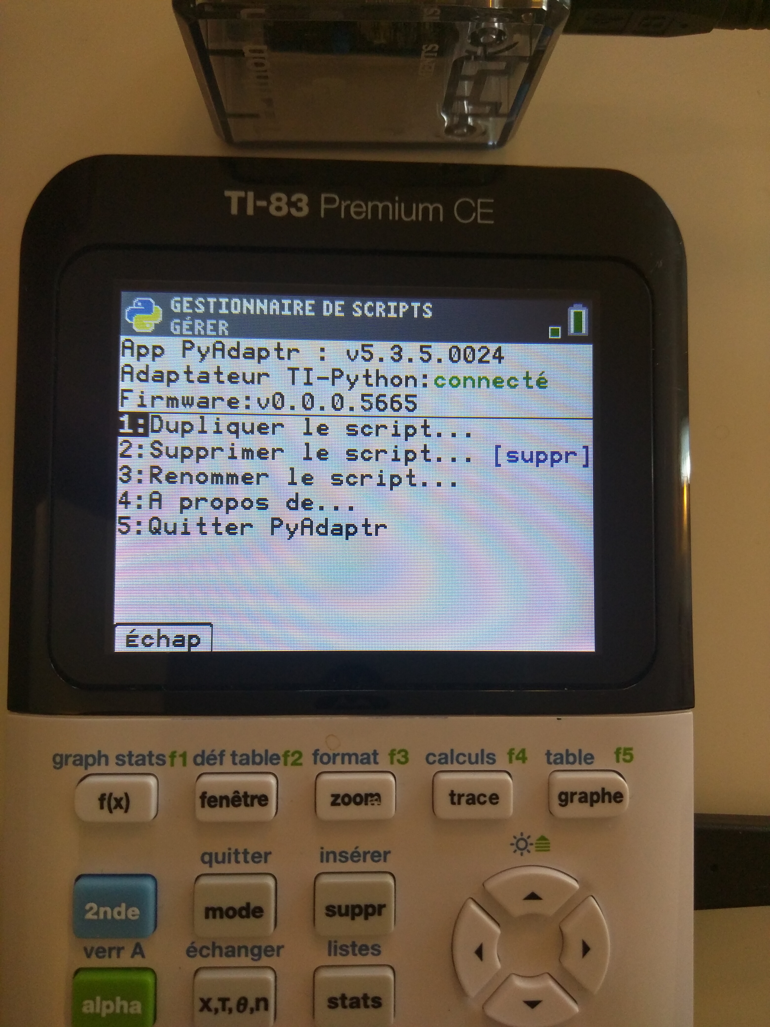
Matching exactly nearly every “public” module API was not successful. I tried the USB descriptor, FAT filesystem, CircuitPython output without any luck. I just managed to find that the version number displayed by the calculator was somewhat linked to the identifier of the MSC storage, but I did not manage to duplicate the original.
Less trivial things
I was pretty sure that there was something “not public” going on, so I ended up using a cheap Chinese logic analyser (a clone of an old Saleae hardware) with Pulseview of the sigrok project. It very conveniently decodes Full speed USB protocol, but the logic analyser hardware is limited to 24 MHz sample rate (and not very reliability at this frequency), and as the Full speed USB bus is 12 MHz, the capture is “at the limit”, resulting in some frames not being decoded. It took me a lot of retries to have a good idea of what was happening.
This is the most interesting capture. This is one of the last packet, just before the calculator try to update the module.
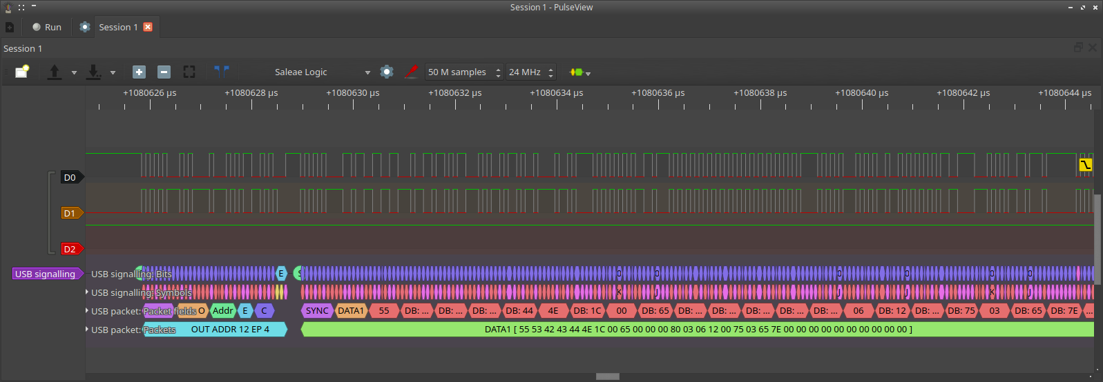
After digging into the useful USB MSC specification (which is pretty short), SCSI commands, this proved to be an unknown INQUIRY query, on an not existing LUN. After several tries, it was clear that this query was some sort of validation of the firmware. The payload was different every time, and also the response.
How to replicate this ? After a lot of thinking, I ended up writing a small program on the computer to send such requests to the module, connected under a debugger. After reading CircuitPython code, I was aware that the USB responses are prepared into a buffer, So I made the computer send the request (not reading the response), and dumped the RAM of the CPU.
As for a specific query the response is always the same, I searched for the corresponding bytes in memory and found them !
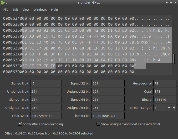
The rest of the process was figuring how this buffer is filled. I just put a watchpoint using gdb, and by dumping the machine instructions, it was clear that this is just a memcopy from the flash ! So the calculator is asking for a bit of flash to compare it to its own version of the firmware.
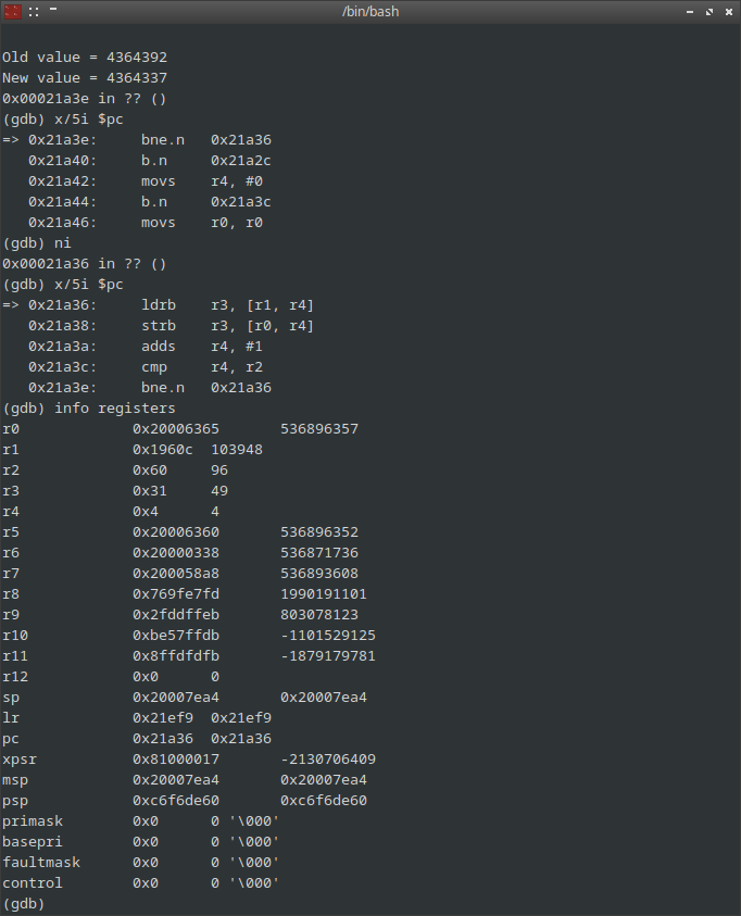
This is a mixed result. The process is very simple to replicate, but it is needed to have a complete copy of the original firmware…
After repeating the procedure, I managed to found that the displayed version of the module was important. It is just the same process (INQUIRY on a not existing LUN), with a static response.
Putting it all together
So now that everything was clear in my mind, I evaluated 3 scenarios : 1. Emulating completely the module on a Raspberry Pi Zero in OTG 2. Using a custom bootloader, jumping into a payload in the FAT space of the original firmware, so the firmware will be here for the validation, but this leaves only 64kB of flash space 3. Adding an SPI flash to the Arduino Zero to store the original firmware, and using a custom CircuitPython on the main flash.
Option 1 and 2 are possible, but for 1. the USB gadget code of the linux kernel is very well written (lot and lot of error checking, …) so it seemed a little bit hard to tinker with.
I worked for a time on option 2 with some promising results but there is still something missing in my implementation, and I was tired of the difficulty of doing USB capture with my logic analyser, so I gave up for now.
So I ended up on option 3, which was pretty straightforward. The code is a little bit ugly, but it is just for the proof of concept.

In the meantime, there was an april fool on TI-Planet about running a the giac CAS engine on the module, so why not ?
I ended up converting the custom CircuitPython in merely a USB/serial converter to a Raspberry Pi Zero, which will boot straight into a Python interpreter on its serial port.
Unfortunately, the calculator does not want to supply enough current, so an external battery is needed. The Arduino Zero, is a bit large, but it can be replaced with an Adafruit Feather M0 Express, which come with an adequate SPI flash to replicate this build.
I cheated a little bit in the video, the Raspberry Pi is sshing my desktop computer to run Python as I have some trouble compiling giac for the Raspberry Pi.