RF plugs clean integration
Introduction
Since I’m lazy, I wanted to control remotely two floor lamps in my house. I bought some cheap RF outlets, but I did not want to have another ugly looking and always lost remote control in the house. So a clean solution was needed !
This is the kind of RF plug I used :
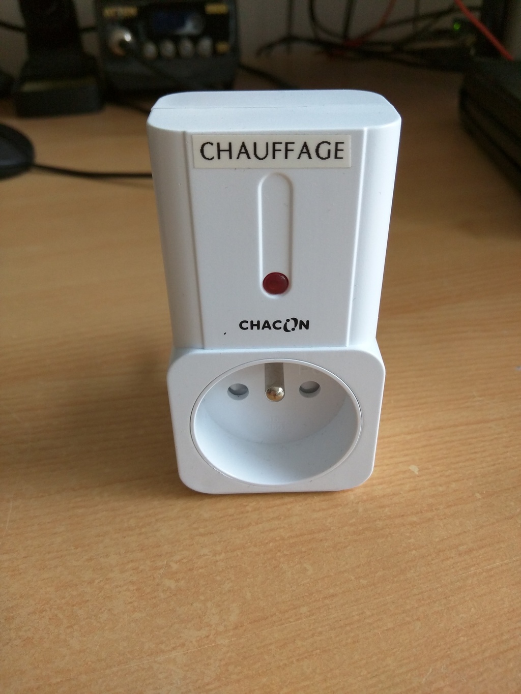 |
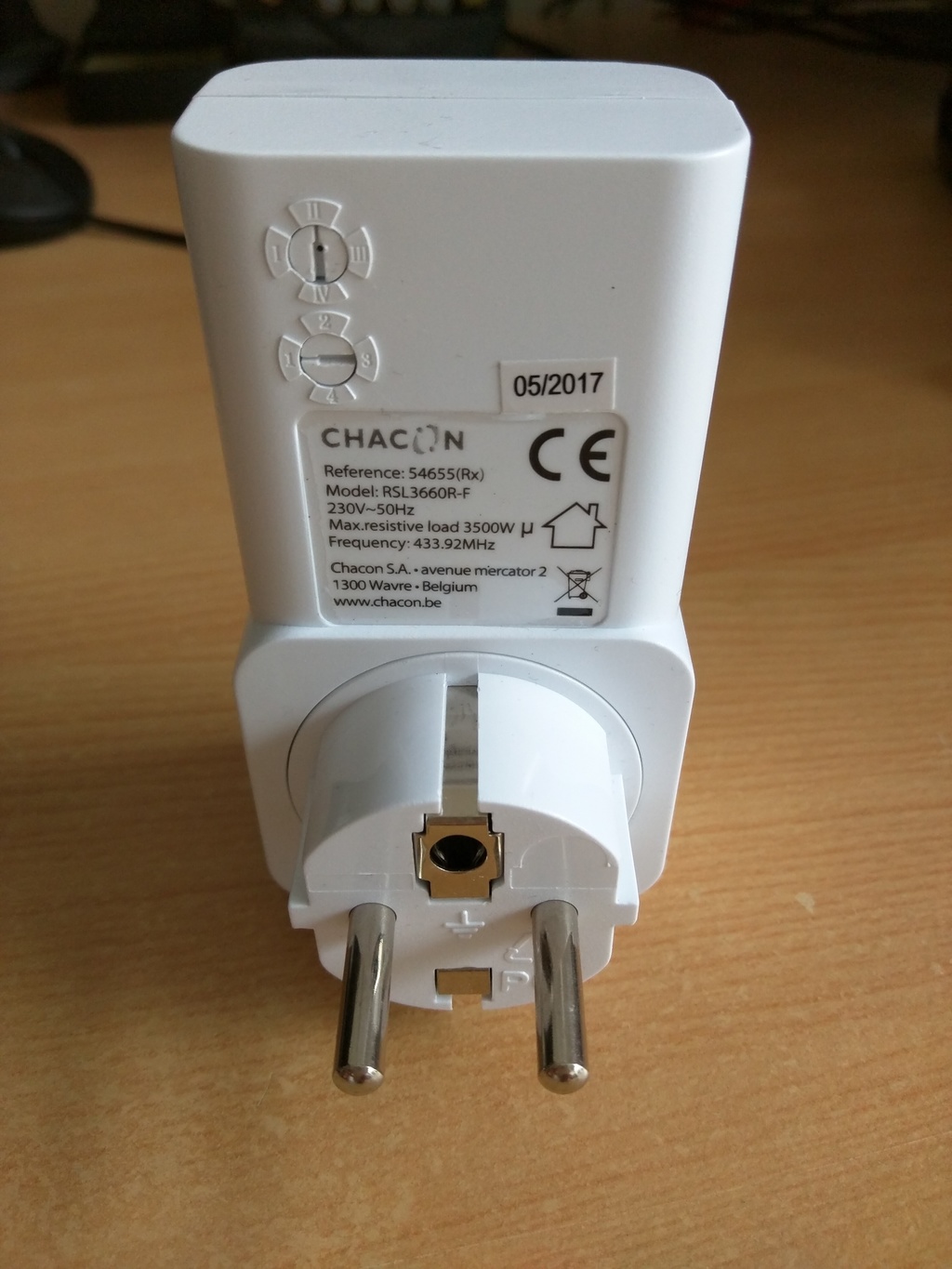 |
 |
 |
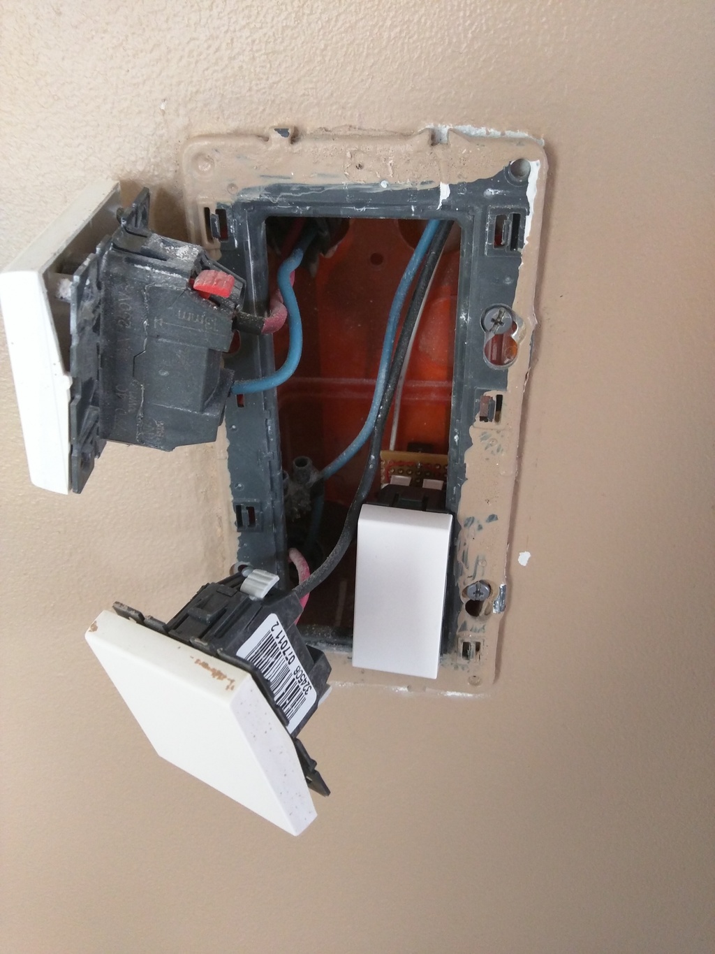
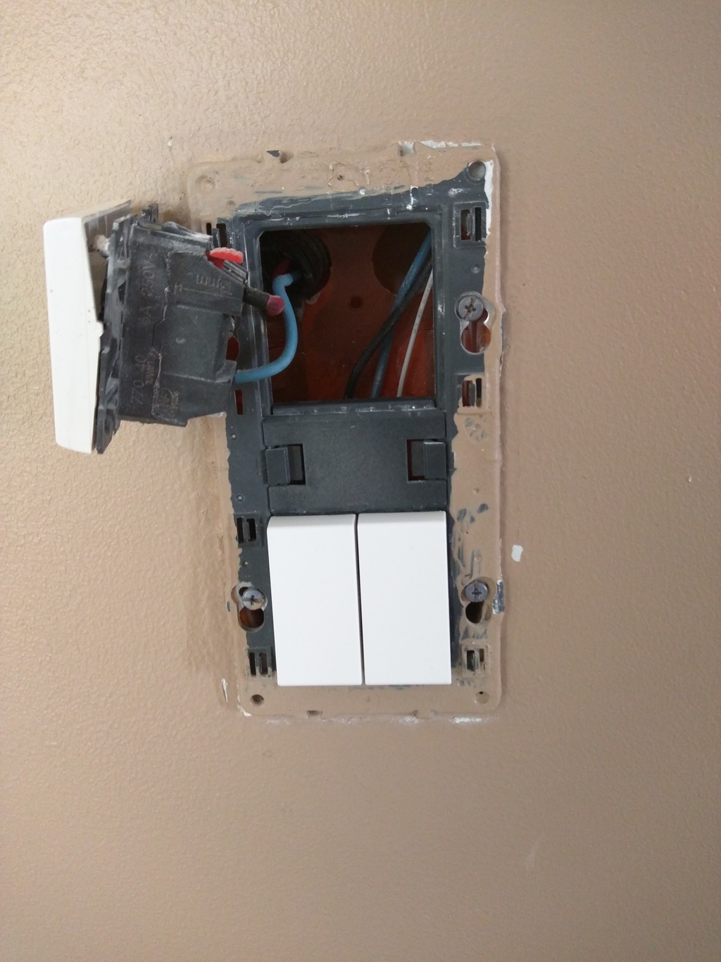
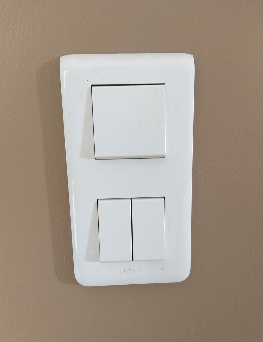
The idea was to add a standard light switch in an existing box. This is the kind of switch I’m using in my house :
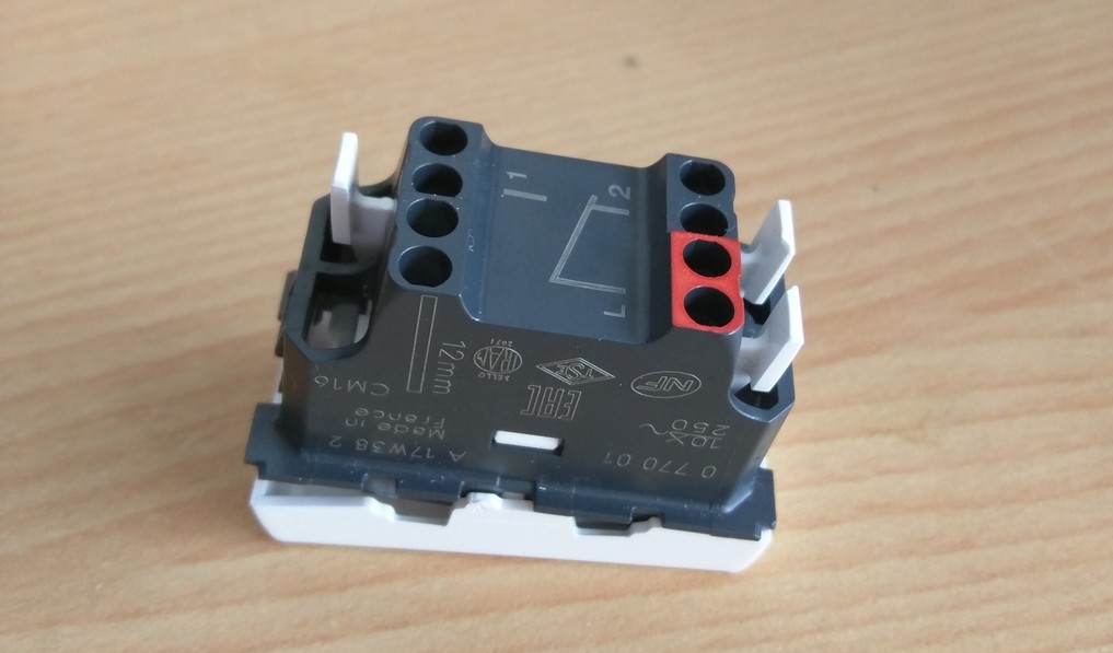
When the switch in installed in the box, there is a little bit less than 1.7 cm available on the back of the switch. This is enough to add a RF backpack to it !
Figuring out the protocol
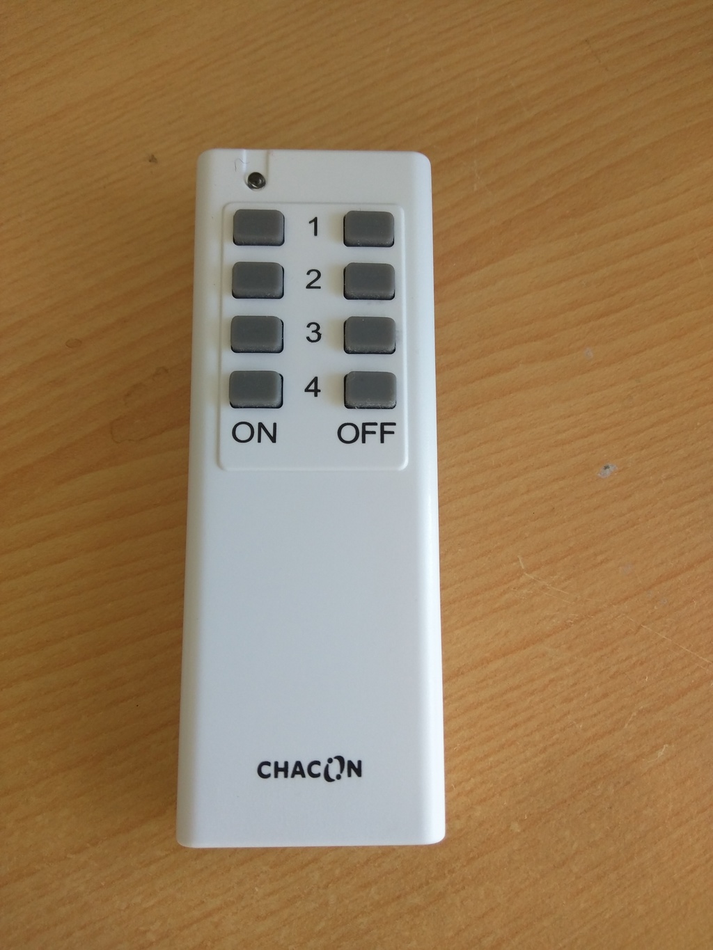
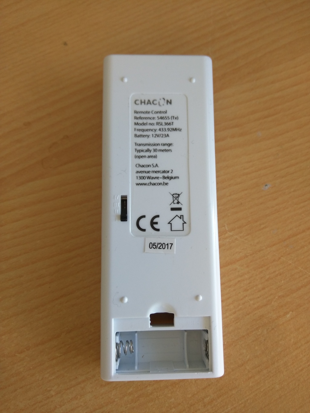
I disassembled the remote control to find the chip used, but I did not find the exact datasheet, and I also wanted to play with the RTL-SDR dongle I have. I quickly recorded a wav file of the modulated signal by using gqrx. It may have been easier to do this with an oscilloscope or logic analyzer, but also less fun :)
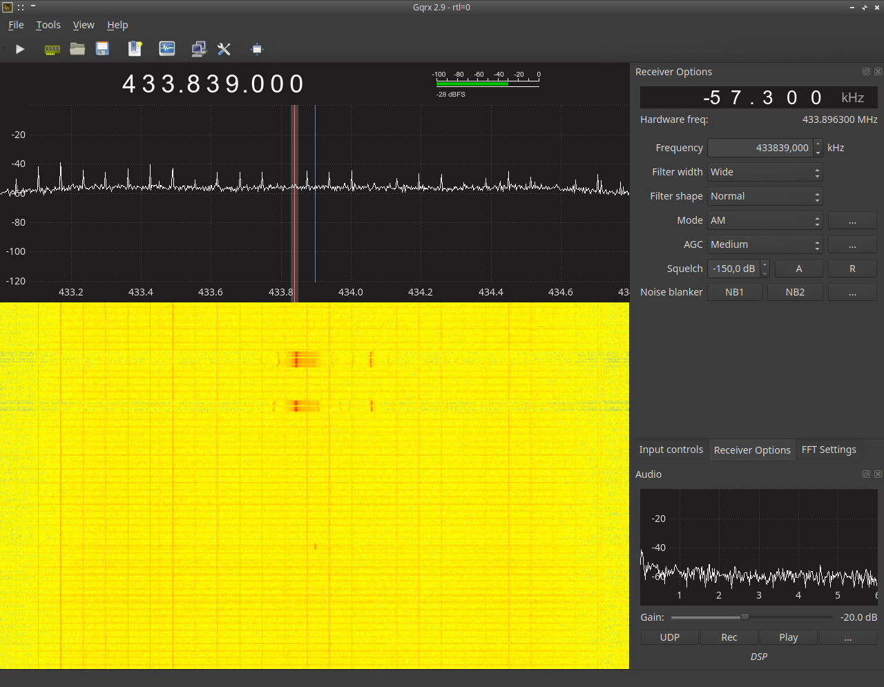
By chossing an AM modulation in gqrx, I got the folowing wav file :
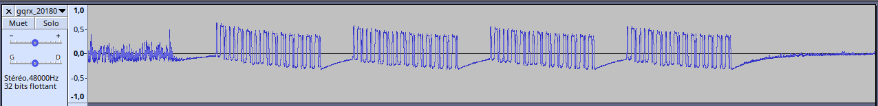
We clearly see the retransmissions of a single key press. Zooming into gives us this :
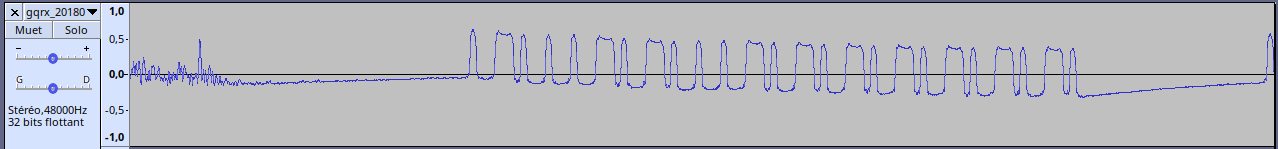
After trying several channels/buttons combinations on the remote, the encoding of the signal is easy to figure :
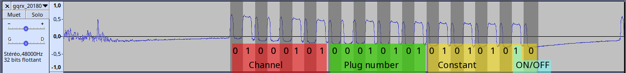
For this one, the transmitter was on channel 2, plug 1 and ON.
Replicating the signal
I used an ATtiny85, as I it is small enough and available in my parts drawers. It is compatible with the arduino environment by using this ATTinyCore, and rc-switch library provides everything needed for the handling the RF transmission. In fact, my plugs are working with all the default values of the library !
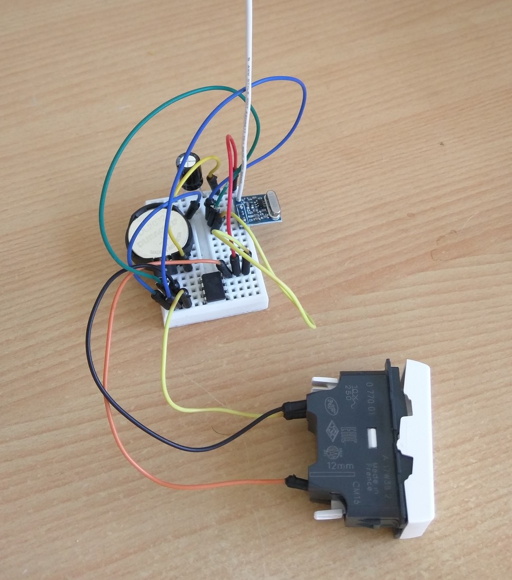
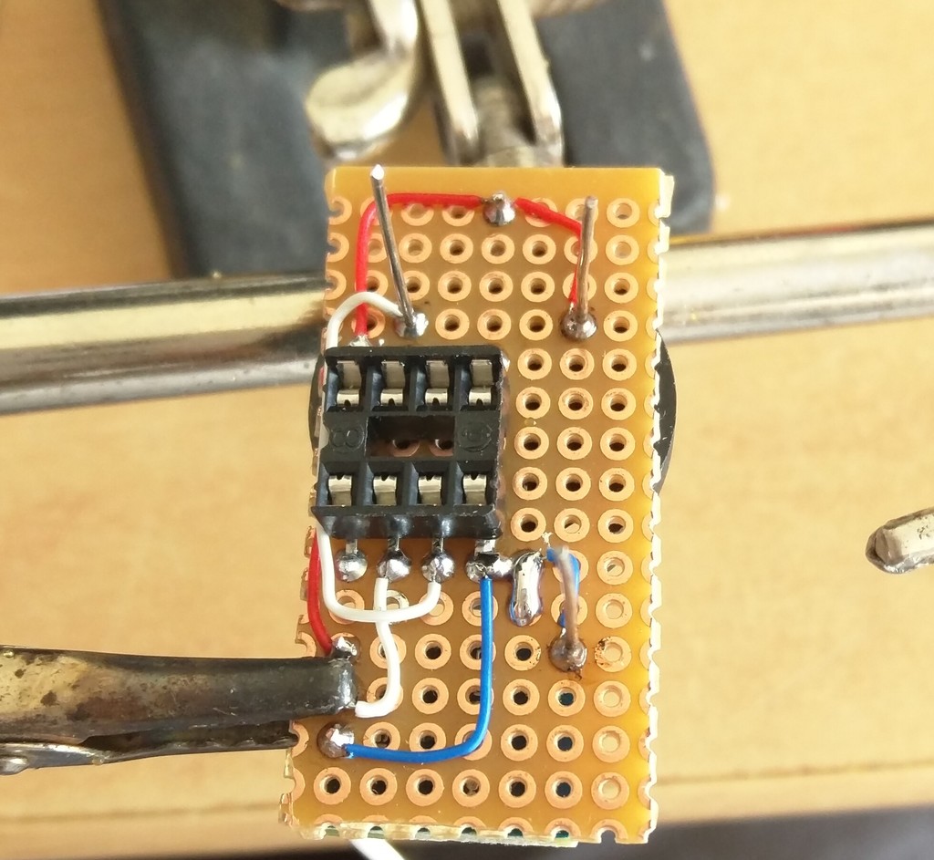
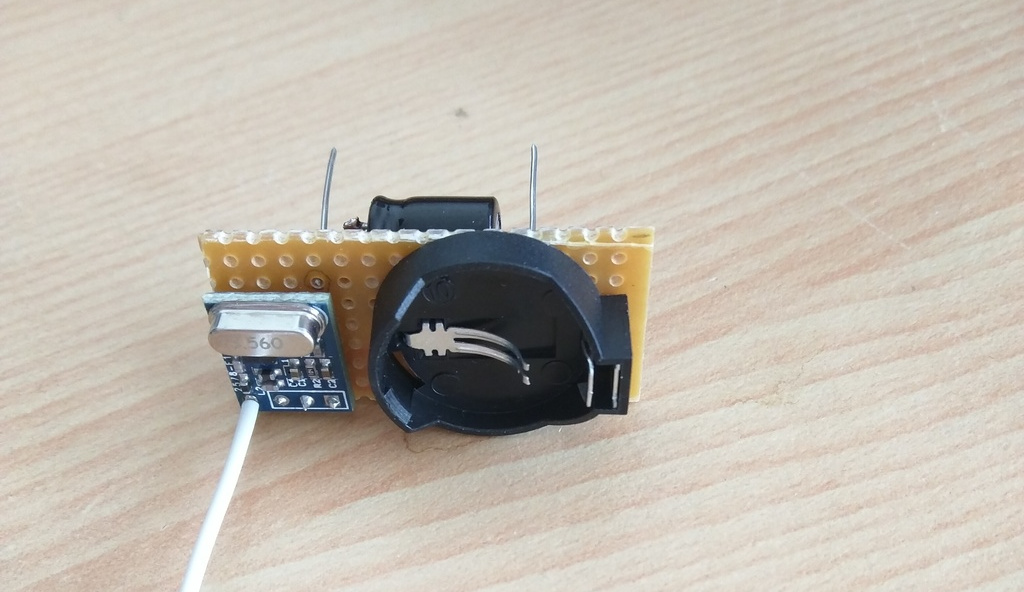
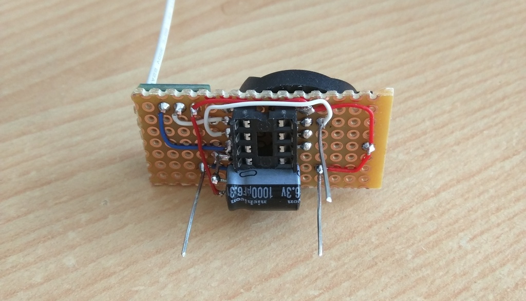
The actual circuit is pretty simple :
- a CR2032 battery
- a capacitor across it (borrowed from a dead motherboard, and having a very low leakage current)
- the ATtiny85
- a 433 MHz transmitter (generic one based on SYN115), connected to arduino pin 3
- a switch, connected to arduino pin 4, and to either VCC or GND depending on its position
Using pin 3 and 4 leaves the ICSP pins free, so the programmer can stay connected during testing.
As it will be battery powered, some care was taken to not deplete it too fast :
- sleeping the ATtiny
- not using pull up on the switch
- verifying the power consumption of the other parts while idle
With all of this, the power consumption is about 0.3 µA when sleeping, so a typical CR2032 of about 200 mAh should last more than needed. I did not measure the energy needed for one transmission to estimate the real lifetime, so I will see when I will have to replace it…
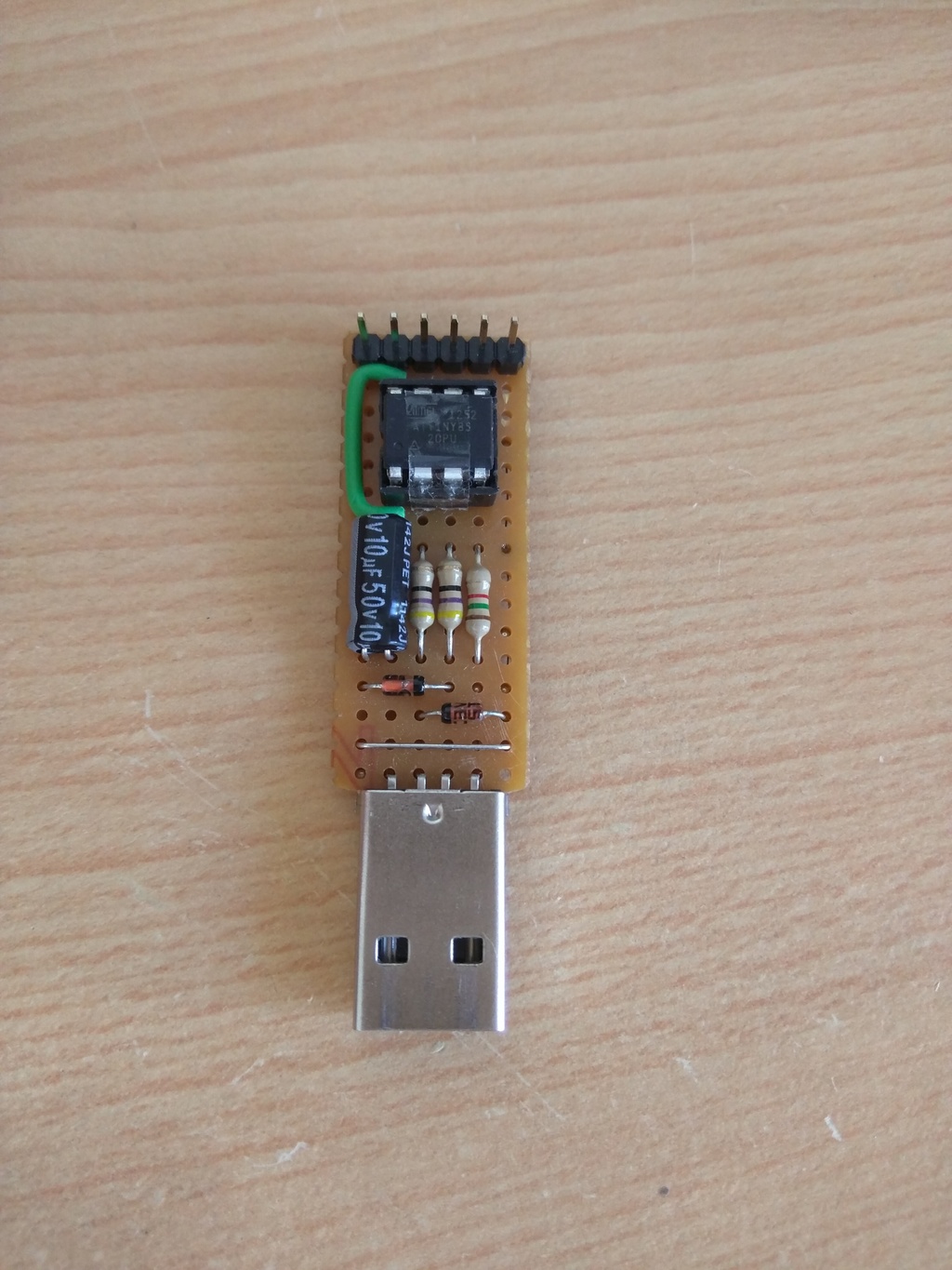
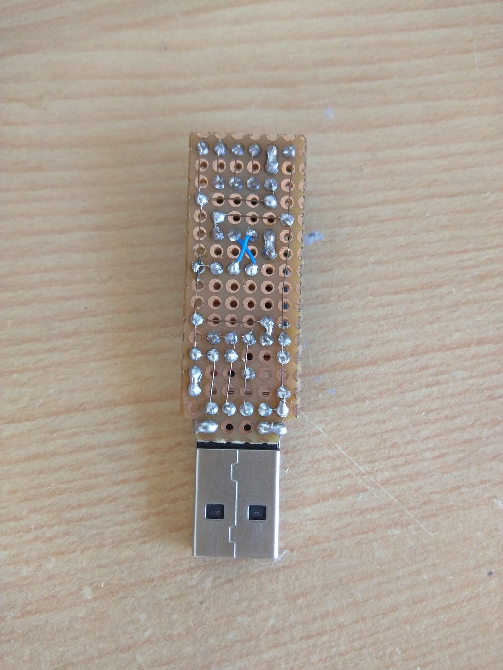
I’m using a custom made Little Wire to program the circuit. It is compatible with USBtinyISP, and does also a lot more. Combined with Micronucleus bootloader, it’s a very useful and easy to use platform (I think it deserves its own post).
 |
 |
From the software site, the pin change interrupt was tricky to implement as there was contradictory statements about it, and the ATtiny core does not provide it. So direct register manipulation was the answer, but it is easy enough.
Here is the full listing :
#include <avr/sleep.h>
#include <avr/power.h>

const byte buttonPin = 4;
const byte interrupt = PCINT4;
const byte txPin = 3;

#include <RCSwitch.h>

// Channels & id : bitmap = {1: '00010101', 2: '01000101', 3: '01010001', 4: '01010100'}
// Code : bitmap[channel] + bitmap[plugnum] + '0101010' + ('1' if on else '0')
RCSwitch mySwitch = RCSwitch();

ISR(PCINT0_vect) {
  static boolean state;
  boolean newState, first = true;
  while((newState = digitalRead(buttonPin)) != state) {
    if(first) // Need to wait a bit between commands
      first = false;
    else
      delayMicroseconds(10000);
    if(digitalRead(buttonPin))
      mySwitch.send("000101010001010101010101"); // ON
    else
      mySwitch.send("000101010001010101010100"); // OFF
    state = newState;
  }
}

void setup()
{
  // Disable ADC (about 300 µA !) & all peripherals
  ADCSRA &= ~(1<<ADEN);
  power_all_disable();

  mySwitch.enableTransmit(txPin);
  mySwitch.setRepeatTransmit(4);

  for(int i=0;i<6;i++) pinMode(buttonPin, INPUT_PULLUP);
  pinMode(buttonPin, INPUT);
  pinMode(txPin, OUTPUT);

  // Enable pin change interrupt
  GIMSK |= _BV(PCIE);
  PCMSK |= _BV(interrupt);
}

void loop()
{
  set_sleep_mode(SLEEP_MODE_PWR_DOWN);
  sleep_enable();
  sei();
  sleep_mode();
  sleep_disable();
  cli();
}
Putting it all together
I made a small PCB, with 3 long pins that will be plugged inside the ZIF sockets of the switch. The pictures are speaking for themselves :
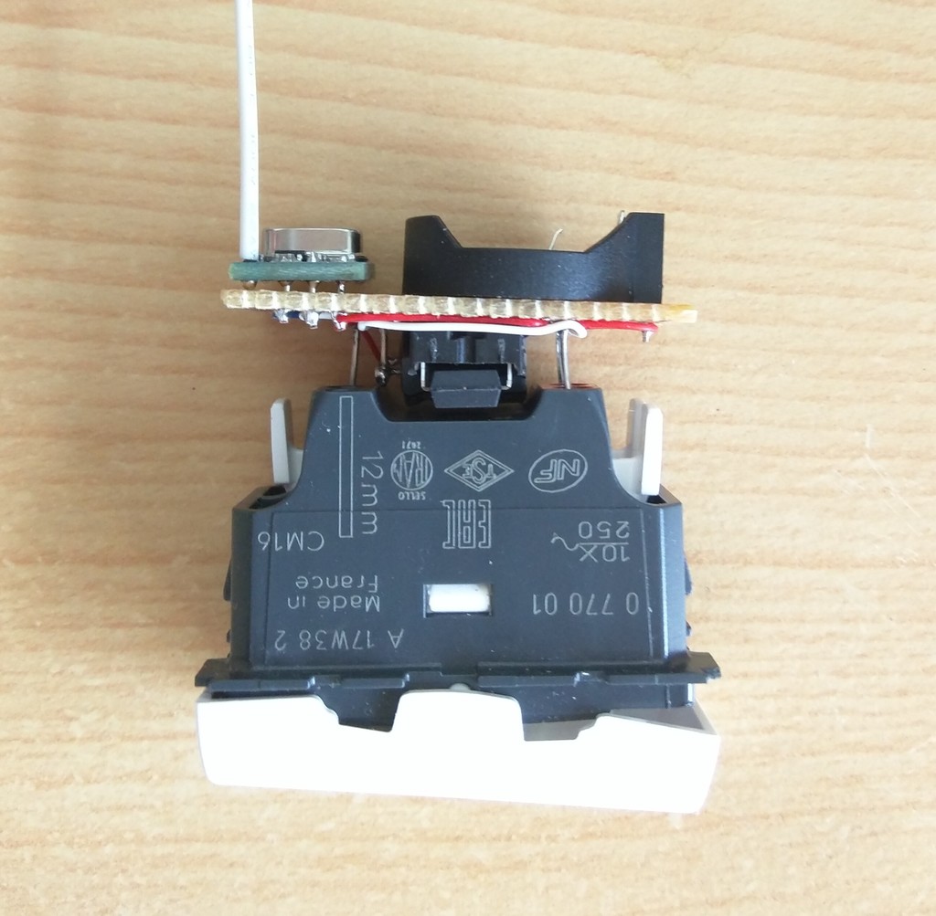
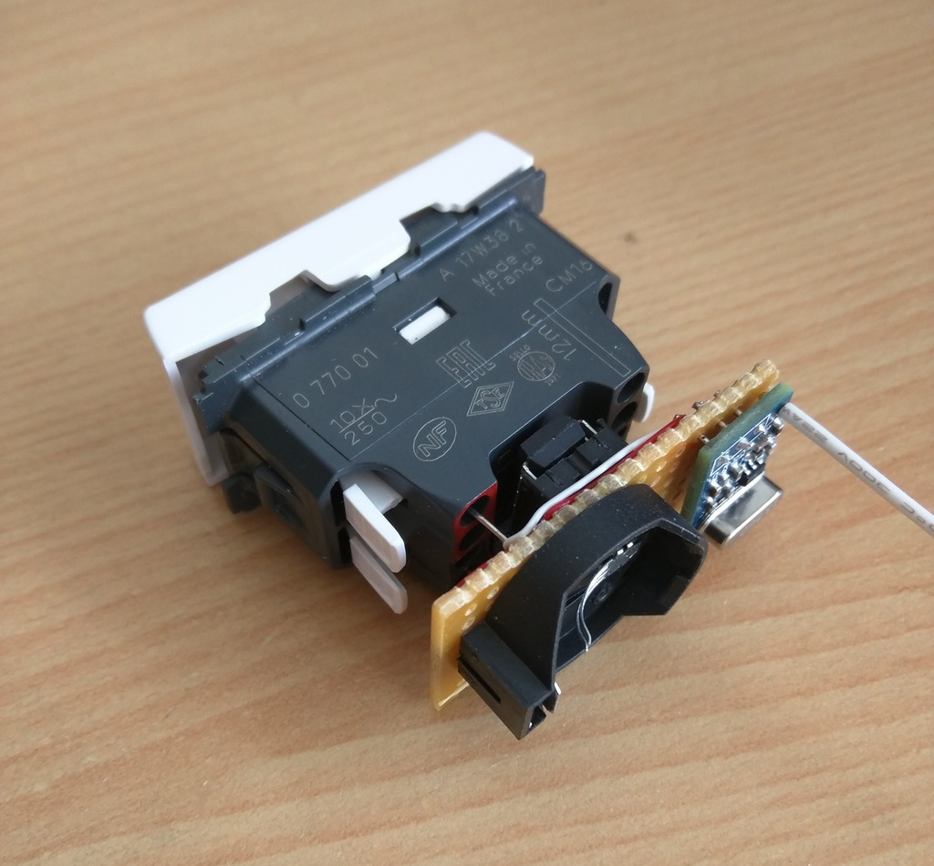
Done !
The next step may be to replace the very noisy relays inside the plugs…