Adding a Raspberry Pi inside a NumWorks calculator
I was having a Raspberry Pi Zero sitting on my desk for a long time, searching for something to do with it. I also wanted to to learn STM32, mainly DMA and interrupts. As the calculator is powered by an STM32F412, why not put them together ?
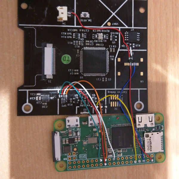
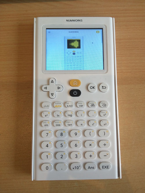
TL;DR, the result:
The idea was to add an application on the calculator, which will display the output of the Raspberry Pi, and send keystroke from the keyboard to it.
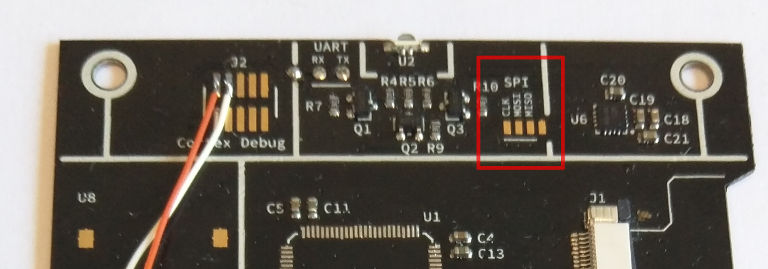
I have already used fbtft on a Raspberry Pi to drive a display over SPI, and the NumWorks has some pads exposing an SPI bus, so this should be easy !
Displaying data from SPI
The calculator firmware already does all the hard work (initializing the display), and provides an API to control the display. In fact, it is driven by the FSMC (Flexible Static Memory Controller), so from the CPU perspective, the display is accessible on two static addresses, one for command, one for data, 16 bits wide.
For this application the only command needed is the one which sets the area where the pixels will be displayed. Fortunately, it is already implemented in the firmware. Pushing pixel is as simple as writing each sequentially to the data address, and they will be displayed from left to right and top to down, like in a standard monitor.
So pixels just needs to be copied from the SPI controller to the display address. Copying pixels like this is an easy task for the DMA engine.
The setup of the window is done before each frame, using the unused MISO pin of the SPI bus, acting as a software chip select. So when MISO goes low, an interrupt is fired, the software chip select on the SPI controller is set (to accept incoming data) and the window is configured in the display controller, covering the entire screen.
Setting the window requires about 3 µs, so the first word coming from the DMA must arrive after this delay. Hopefully, on the Raspberry Pi side, there is even enough delay between the chip select and the first byte clocked in (about 10 µs).
Setting up the GPIO
The SPI pins must be configured in alternate mode, in order to be connected internally to the SPI Controller. The MISO pin is left as a normal GPIO as it is used to trigger an interrupt.
GPIOA.MODER()->setMode(5, GPIO::MODER::Mode::AlternateFunction);
GPIOA.AFR()->setAlternateFunction(5, GPIO::AFR::AlternateFunction::AF5);
GPIOA.MODER()->setMode(6, GPIO::MODER::Mode::Input);
GPIOA.MODER()->setMode(7, GPIO::MODER::Mode::AlternateFunction);
GPIOA.AFR()->setAlternateFunction(7, GPIO::AFR::AlternateFunction::AF5);
Setting up the SPI Controller
The configuration of th SPI controller is very simple. It is set in 16 bits mode, RXONLY (as the MISO pin is reused ad chip select), and software chip select.
SPI1.CR1()->setRXONLY(true);
SPI1.CR1()->setSSI(true); // Software chip select
SPI1.CR1()->setSSM(true); // Software chip select mode
SPI1.CR1()->setDFF(true); // 16 bits
SPI1.CR1()->setSPE(true); // enable
Setting up the DMA controller
In order for the DMA to work, it is needed to select the right DMA controller, stream and channel. After that, it is needed to configure, the source address (here the SPI1 data register), the destination address (display controller data address), source and destination data width (16 bits), the mode (circular), and the number of words to transfer (here 1, because we are in circular mode). There is no need to increment source/destination address it is always the same.
DMAEngine.SPAR(DMAStream)->set((uint32_t)SPI1.DR()); // Source
DMAEngine.SM0AR(DMAStream)->set((uint32_t)Ion::Display::Device::DataAddress); // Destination
DMAEngine.SNDTR(DMAStream)->set(1); // Number of items
DMAEngine.SCR(DMAStream)->setCHSEL(3); // SPI Channel
DMAEngine.SCR(DMAStream)->setDIR(DMA::SCR::Direction::PeripheralToMemory);
DMAEngine.SCR(DMAStream)->setMSIZE(DMA::SCR::DataSize::HalfWord);
DMAEngine.SCR(DMAStream)->setPSIZE(DMA::SCR::DataSize::HalfWord);
DMAEngine.SCR(DMAStream)->setCIRC(true); // Circular
DMAEngine.SCR(DMAStream)->setEN(true); // Enable
Setting up the SPI controller to issue DMA requests
This is simply done by enabling the RXDMAEN bit in the SPI control register.
SPI1.CR2()->setRXDMAEN(true); // enable DMA requests
Setting up an interrupt from the MISO pins
This was the tricky part. There is several level of abstraction between the pin and the actual interrupt handler.
First, the EXTI (External interrupt/event controller) must be configured to trigger an interrupt line in the NVIC (Nested vectored interrupt controller).
Then, the NVIC line must be enabled, and the according interrupt handler defined. Do not forget to acknowledge the interrupt in the handler !
SYSCFG.EXTICR2()->setEXTI(Ion::Rpi::Device::ChipSelectPin, Ion::Rpi::Device::ChipSelectGPIO);
EXTI.RTSR()->set(Ion::Rpi::Device::ChipSelectPin, true);
EXTI.FTSR()->set(Ion::Rpi::Device::ChipSelectPin, true);
NVIC.NVIC_ISER0()->set(23, true);
The interrupt handler
It does two things :
when CS goes low, it activates the software chip select of the SPI controller, and then it triggers the configuration of the window in the display controller.
when CS goes high, it disactivates the software chip select of the SPI controller. Any data received on the SPI will be discarded.
void rpi_isr() {
  EXTI.PR()->set(Ion::Rpi::Device::ChipSelectPin, true);

  if(GPIOA.IDR()->get(6)) {
    SPI1.CR1()->setSSI(true);
  } else {
    Ion::Display::Device::setDrawingArea(KDRect(0,0,320,240), Ion::Display::Device::Orientation::Landscape);
    *Ion::Display::Device::CommandAddress = Ion::Display::Device::Command::MemoryWrite;
    SPI1.CR1()->setSSI(false);
  }
}
Limitations
There is no error handling if something goes wrong, the whole chain can be blocked. This may occur mainly on the SPI controller. If the DMA does not read the data fast enough, it will be stuck, waiting for an acknowledgement of the error.
Sending the Raspberry Pi display over the SPI bus
At first, I planned to use fbtft as is, but after diving into the code, it quickly appears that it will not be usable, because it expects a direct access to the display controller, in order to optimize the pushing of pixel (by limiting to area that have changed on the screen). I did not want to implement such feature on the calculator, so decided to write my own.
By using concept and code from fbtft, an another driver written by Sprite_tm and also from the in-kernel vfb driver, I put together a “quick and dirty” linux module, which is doing only what I needed: pushing the whole framebuffer over the SPI bus.
The display is 320x240 pixel, 16bpp each, so each frame is 1228800 bits. The maximum SPI frequency of the STM32F412 is 50 MHz, but the Raspberry Pi cannot generate exactly it. After testing at 62.5 MHz, it seems to work well, so, in theory, the maximum framerate is \(\left(\frac{1228800}{62.5 \times 10^6}\right)^{-1} \approx 50\) fps.
Implementing the Keyboard
This is the “active” part of the application on the calculator (as SPI and DMA are running in the background). The calculator simply sends the result of the keyboard scan routine of the firmware (a 64 bit bitfield) to the RPi over the UART.
On the RPi side, a daemon listen on the UART and generates keycodes to the kernel using uinput.
The mapping is a bit tedious, and may be much better with a custom keymap on the Linux side. I did not go this way, as a external bluetooth keyboard is still usable (and I don’t know if it is possible to have different keymaps on several keyboard).
The calculator keyboard has only 46 keys so in oder to map enough keys, the buttons “x,n,t” and “var” are used to switch between standard keys and numbers. Not all the keys of a standard keyboard are mapped. This point deserve to be enhanced…
The mouse simply relies on the mouse emulation of X.Org. It is triggered by pushing the power button.
Calc          Keymap 1          Keymap 2

{"left",      {KEY_KP4,         KEY_KP4}},
{"up",        {KEY_KP8,         KEY_KP8}},
{"down",      {KEY_KP2,         KEY_KP2}},
{"right",     {KEY_KP6,         KEY_KP6}},
{"ok",        {BTN_LEFT,        BTN_LEFT}},
{"back",      {BTN_RIGHT,       BTN_RIGHT}},
{"home"},     // not handled here
{"power"},    // toggle mouse mode
{NULL},
{NULL},
{NULL},
{NULL},
{"shift",     {KEY_LEFTSHIFT,   KEY_LEFTSHIFT}},
{"alpha",     {KEY_CAPSLOCK,    KEY_CAPSLOCK}},
{"xnt"},      // Switch to first keymap
{"var"},      // Switch to second keymap
{"toolbox",   {KEY_RIGHTALT,    KEY_RIGHTALT}},
{"backspace", {KEY_BACKSPACE,   KEY_ESC}},
{"A",         {KEY_Q,           KEY_F1}},
{"B",         {KEY_B,           KEY_F2}},
{"C",         {KEY_C,           KEY_F3}},
{"D",         {KEY_D,           KEY_F4}},
{"E ,",       {KEY_E,           KEY_F5}},
{"F",         {KEY_F,           KEY_F6}},
{"G",         {KEY_G,           KEY_F7}},
{"H",         {KEY_H,           KEY_F8}},
{"I",         {KEY_I,           KEY_F9}},
{"J",         {KEY_J,           KEY_F10}},
{"K",         {KEY_K,           KEY_F11}},
{"L",         {KEY_L,           KEY_F12}},
{"M 7",       {KEY_SEMICOLON,   KEY_7}},
{"N 8",       {KEY_N,           KEY_8}},
{"O 9",       {KEY_O,           KEY_9}},
{"P (",       {KEY_P,           KEY_5}},
{"Q )",       {KEY_A,           KEY_MINUS}},
{NULL},
{"R 4",       {KEY_R,           KEY_4}},
{"S 5",       {KEY_S,           KEY_5}},
{"T 6",       {KEY_T,           KEY_6}},
{"U *",       {KEY_U,           KEY_KPASTERISK}},
{"V /",       {KEY_V,           KEY_KPSLASH}},
{NULL},
{"W 1",       {KEY_Z,           KEY_1}},
{"X 2",       {KEY_X,           KEY_2}},
{"Y 3",       {KEY_Y,           KEY_3}},
{"Z +",       {KEY_W,           KEY_KPPLUS}},
{"space -",   {KEY_SPACE,       KEY_KPMINUS}},
{NULL},
{"? 0",       {KEY_M,           KEY_0}},
{"! .",       {KEY_COMMA,       KEY_COMMA}},
{"x10^x",     {KEY_LEFTCTRL,    KEY_LEFTCTRL}},
{"ans",       {KEY_LEFTALT,     KEY_LEFTALT}},
{"exe",       {KEY_ENTER,       KEY_EQUAL}},
The Raspberry Pi
Powering up the Pi
The initial RPi I used was a Zero (without W). It seemed to work well when powered by 2.8 V (the internal regulated voltage on the calculator), and there is provision on the board for an SD card reader, and a transistor to control its power supply. I decided to reuse the SD power supply pads to control the power going to the RPi.
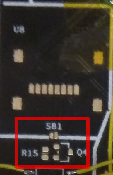
But after, I realized that it will be sad to not include WiFi, so I ordered a “W” version. It turns out that it is not happy with 2.8 V. The datasheet of the WiFi chip states that it needs at least 3 V. Disabling the WiFi chip (“dtoverlay=pi3-disable-wifi” in config.txt) made te RPi working at 2.8 V
So, I decided to power the RPi directly from the battery. As I can no longer use the footprint of the SD card, I soldered the transistor and pull up resistor “free style”, on a non connected pin of the SD cart socket footprint.
I used an NTR1P02LT1 and a 10 kΩ resistor, but any P channel “logic level” MOSFET that can handle at least 100 mA should be good.
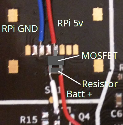
There is no problem with the voltage level, as all the pins used on the STM32 are 5 V tolerant.
The RPi is powered up upon entering the application, and powered down when the calculator is powered down. So it is possible to leave or enter the RPi application as needed.
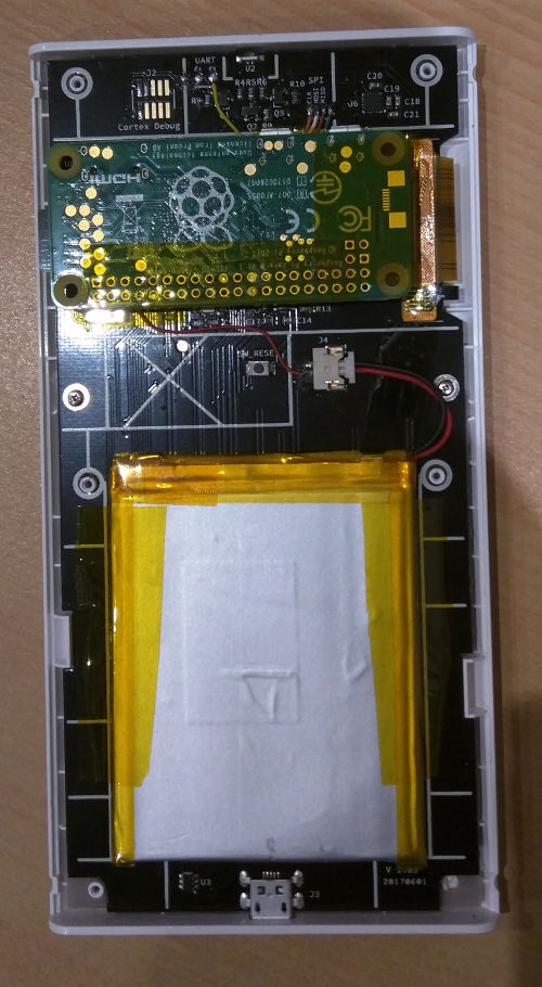
Putting it into the calculator
The RPi fits nicely inside the calculator. There is a row with no components where the connectors of the RPi resides. I made it stay in place with double sided adhesive on the HDMI connector, and on the display connector of the calculator.
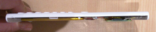
Unfortunately, this is a little to thick to replace the original cover (with the vertical tabs cut out), but it is possible to leave the cover in place :
Software configuration
Raspberry Pi
GitHub repo : https://github.com/zardam/spifb
It is just needed to install the kernel headers, compile, install and auto load the module.
sudo apt-get install raspberrypi-kernel-headers build-essential
git clone https://github.com/zardam/spifb.git
cd spifb
make -C /lib/modules/$(uname -r)/build M=$PWD
sudo make -C /lib/modules/$(uname -r)/build M=$PWD modules_install
sudo depmod -a
/etc/modules
spi-bcm2835
spifb
uinput
/boot/config.txt
dtparam=spi=on

# Disable HDMI output, saves some power
hdmi_blanking=2

# Enable the mini uart (/dev/ttyS0 on a PI Zero W)
enable_uart=1

# Disable LED, saves some power
dtparam=act_led_trigger=none
dtparam=act_led_activelow=on
Then there is two possibilities :
direct use of the framebuffer. This is the simplest method, but the hardware acceleration of the RPi GPU will not be available
using fbcp to copy the normal framebuffer (fb0) to the SPI framebuffer (spi1). The copy introduce some CPU overhead, but hardware acceleration is available, and it is possible to scale the framebuffer, as a resolution of 320x240 is nearly unusable.
Direct use of the framebuffer
The configuration is the same as using fbtft.
/boot/cmdline.txt
fbcon=map:10
X Server
sudo apt-get install xserver-xorg-video-fbdev
/usr/share/X11/xorg.conf.d/99-fbdev.conf
Section "Device"
  Identifier "myfb"
  Driver "fbdev"
  Option "fbdev" "/dev/fb1"
EndSection
fbcp
I used this fork. CMake is needed to build it.
sudo apt-get install cmake
git clone https://github.com/Oper8or/rpi-fbcp.git
cd rpi-fbcp
mkdir build
cd build
cmake ..
make
/boot/config.txt
hdmi_force_hotplug=1
hdmi_cvt=640 480 60 1 0 0 0
hdmi_group=2
hdmi_mode=87
/etc/systemd/system/fbcp.service
[Unit]
Description=NumWorks input device
After=systemd-modules-load.service

[Service]
Type=simple
WorkingDirectory=/home/pi/rpi-fbcp/build
ExecStart=/home/pi/rpi-fbcp/build/fbcp
User=root
Group=root
Restart=on-failure

[Install]
WantedBy=multi-user.target
Then, enable and start the service:
sudo systemctl daemon-reload
sudo systemctl enable fbcp
sudo systemctl start fbcp
Keyboard
GitHub repo : https://github.com/zardam/uinput-serial-keyboard
git clone https://github.com/zardam/uinput-serial-keyboard
cd uinput-serial-keyboard
gcc uinput.c -o uinput
lxkeymap needs to be disabled in the lxde session configuration (just use the GUI tool).
The linux serial console must be disabled. In /boot/cmdline.txt, remove:
console=serial0,115200
/etc/systemd/system/nwinput.service
[Unit]
Description=NumWorks input device

[Service]
Type=simple
WorkingDirectory=/home/pi/uinput-serial-keyboard/
ExecStart=/home/pi/uinput-serial-keyboard/uinput
User=root
Group=root
Restart=on-failure

[Install]
WantedBy=multi-user.target
Then, enable and start the service:
sudo systemctl daemon-reload
sudo systemctl enable nwinput
sudo systemctl start nwinput
Calculator
GitHub repo : https://github.com/zardam/epsilon/tree/rpi
On a computer, after installing the NumWorks SDK :
git clone -b rpi https://github.com/zardam/epsilon.git
cd epsilon
make epsilon_flash
Then connect and reset the calculator to flash the custom firmware.
Done ;)
The calculator, browsing its own emulator on the internet:
There is a lot of room for improving the code, and there is certainly things not done the right way, but it was a very interesting project.